


Spiral Fin Tube
Continuously welded helical fin for boiler, economizer and flue gas duty
What Spiral Fin Tube Is
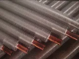
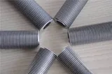
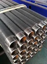
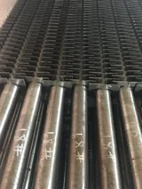
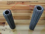
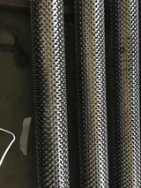
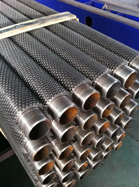
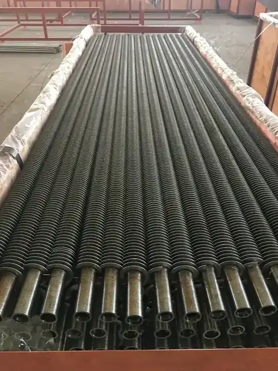
A spiral fin tube carries a steel fin welded continuously along a helix, so fin and tube form a welded metallic path rather than a mechanical grip.
That is what makes it the standard for flue gas duty: the joint survives metal temperatures and thermal cycling that would release a wound fin.
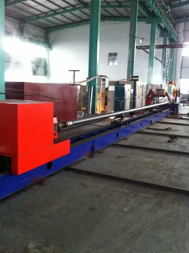
Fanbang runs three spiral fin production lines and can weld fins from 0.3 mm to 2.0 mm thick on base tubes with walls up to 15.0 mm.
Why Engineers Specify It
Welded joint, not a mechanical grip
The fin root is fused to the tube, so high flue gas temperatures do not loosen it.
Heavy wall base tubes accepted
Wall thickness up to 15.0 mm suits pressure parts, not just cooler bundles.
Fin height to 17 mm
Tall fins recover more heat from low grade flue gas in an economizer bank.
Same alloy family on both sides
Steel fin on steel tube keeps the weld metallurgy simple and avoids a dissimilar joint.
Where It Is Used
- Food processing
- Chemical engineering
- Energy and power
- Medicine and pharmacy
- Rail power
- Electromechanical devices
- Military industries
- Domestic gas heaters
Buyers Who Come to Us for This Tube
Boiler and economizer manufacturers
Heat recovery banks in the flue gas path.
Waste heat recovery contractors
Exhaust duty where a mechanically bonded fin would fail.
Process heater builders
Fired equipment with steel-to-steel construction requirements.
What Goes Wrong Without It
Mechanically bonded fins failing in flue gas
A continuous weld carries the heat path and does not rely on contact pressure.
Low grade waste heat going up the stack
Fin heights to 17.0 mm add the surface needed to pull temperature out of the gas.
Pressure part tubes needing fins
Base tube walls to 15.0 mm mean the finned tube can also be the pressure boundary.
Spiral Fin Tube Dimensions
These are the ranges our production lines run. Sizes outside them are quoted case by case rather than assumed.
| Item | Specification |
|---|---|
| Base tube diameter | 15 mm - 70 mm |
| Base tube wall thickness | 2.0 mm - 15.0 mm |
| Fin thickness | 0.3 mm - 2.0 mm |
| Fin pitch | 1.2 mm - 5.0 mm |
| Fin height | 4.0 mm - 17.0 mm |
Materials
| Component | Materials available |
|---|---|
| Base tube | Stainless steel, carbon steel, alloy steel, nickel |
| Fin strip | Carbon steel, stainless steel, alloy steel |
How It Is Made
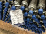
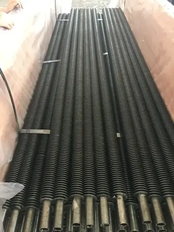
Spiral Fin Tube on the Shop Floor
Inspection and Certification
Every tube passes eddy current and hydrostatic testing, with tensile, flattening, flaring, hardness and chemical analysis carried out on our own equipment. Fin pitch, fin height and finned length are verified as dimensional items in their own right.
The company holds ISO 9001:2015, CE certificate, Production licence for pressure pipe.
What Can Be Changed
- Base tube material and wall thickness within the range above
- Fin material, fin pitch and fin height to the bundle design
- Finned length and bare end length for the tubesheet joint
- Marking, packing and certificate scope for the destination market
Compared With the Alternatives
Against H type fins, a spiral fin gives more surface per metre but less room for ash to fall through, so spiral suits clean and moderately dusty gas while H type suits ash-laden flue gas. Against mechanically bonded tubes, spiral fins tolerate far higher metal temperature.
Use Guide
- Give the flue gas temperature and dust loading - they set fin pitch and fin height more than the duty does.
- Match the fin material to the tube material where corrosion allowance matters; a stainless fin on a carbon tube is available but changes the weld procedure.
- State whether the finned tube is a pressure part, because that governs base tube wall and material certification.
Spiral Fin Tube FAQ
Is the fin welded continuously or in segments?
Continuously along the helix, which keeps an unbroken heat path from fin to tube.
What is the thickest base tube wall you can fin?
15.0 mm, with base tube diameter from 15 mm to 70 mm.
Can you weld a stainless fin onto a carbon steel tube?
Yes. Fin strip in carbon steel, stainless steel or alloy steel can be welded onto stainless, carbon, alloy or nickel base tubes.
What fin pitch do economizers normally use?
It depends on dust loading. Our range is 1.2 mm to 5.0 mm; dirtier gas needs the open end of that range.
Often Compared With
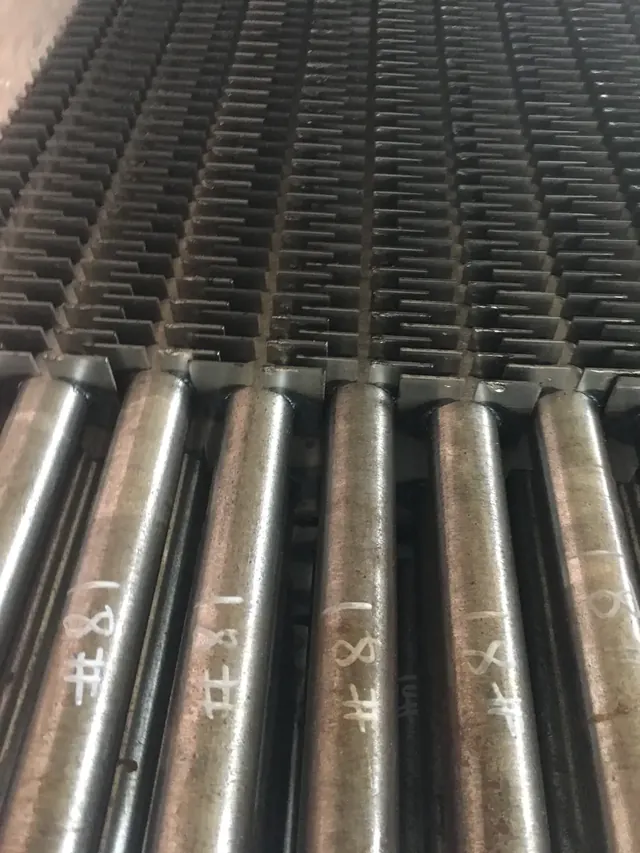 H/HH Fin Tube
Split square fins welded in pairs, leaving a straight ash lane along the tube
Base tube diameter: 25 mm - 73 mm · Base tube wall thickness: 3.0 mm - 6.0 mm
H/HH Fin Tube
Split square fins welded in pairs, leaving a straight ash lane along the tube
Base tube diameter: 25 mm - 73 mm · Base tube wall thickness: 3.0 mm - 6.0 mm
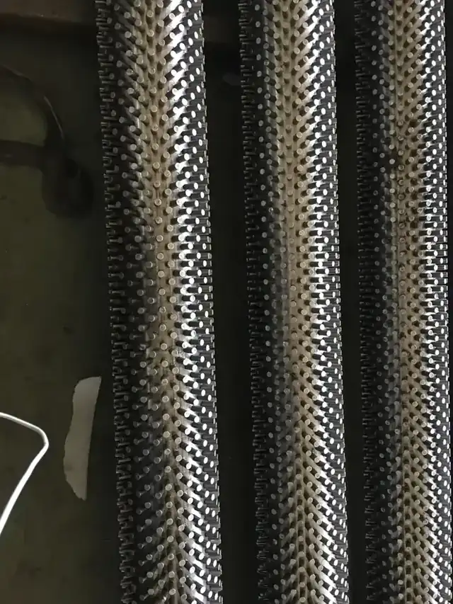 Stud Fin Tube
Individually welded studs for the dirtiest furnace and process heater duty
Base tube diameter: 38 mm - 273 mm · Base tube wall thickness: 3.5 mm - 10.0 mm
Stud Fin Tube
Individually welded studs for the dirtiest furnace and process heater duty
Base tube diameter: 38 mm - 273 mm · Base tube wall thickness: 3.5 mm - 10.0 mm
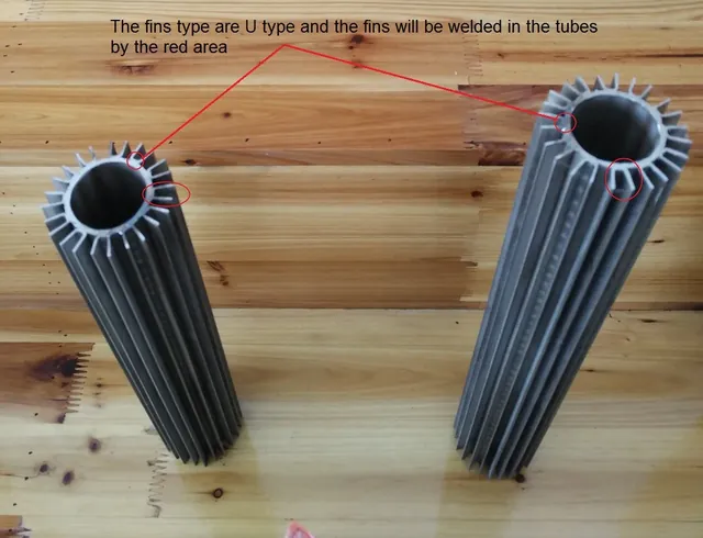 Longitudinal Fin Tube
Straight fins welded along the tube axis for viscous fluids and low velocity gas
Base tube diameter: 12 mm - 273 mm · Base tube wall thickness: 2.11 mm - 25.4 mm
Longitudinal Fin Tube
Straight fins welded along the tube axis for viscous fluids and low velocity gas
Base tube diameter: 12 mm - 273 mm · Base tube wall thickness: 2.11 mm - 25.4 mmIndustries using this tube
Related reading
Quote Spiral Fin Tube From Your Drawing
Send base tube size, wall thickness, fin geometry, material and length. You get a quotation against the drawing, not a catalogue page.
[email protected] · Tel 0086 512 58392615 · Monday to Saturday, 08:30 - 17:30 China Standard Time (GMT+8)