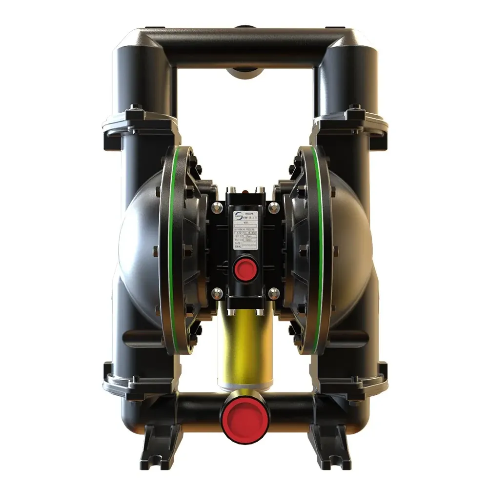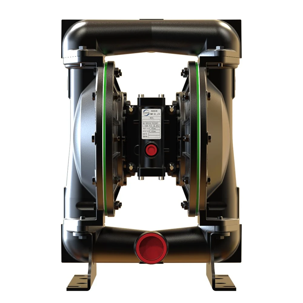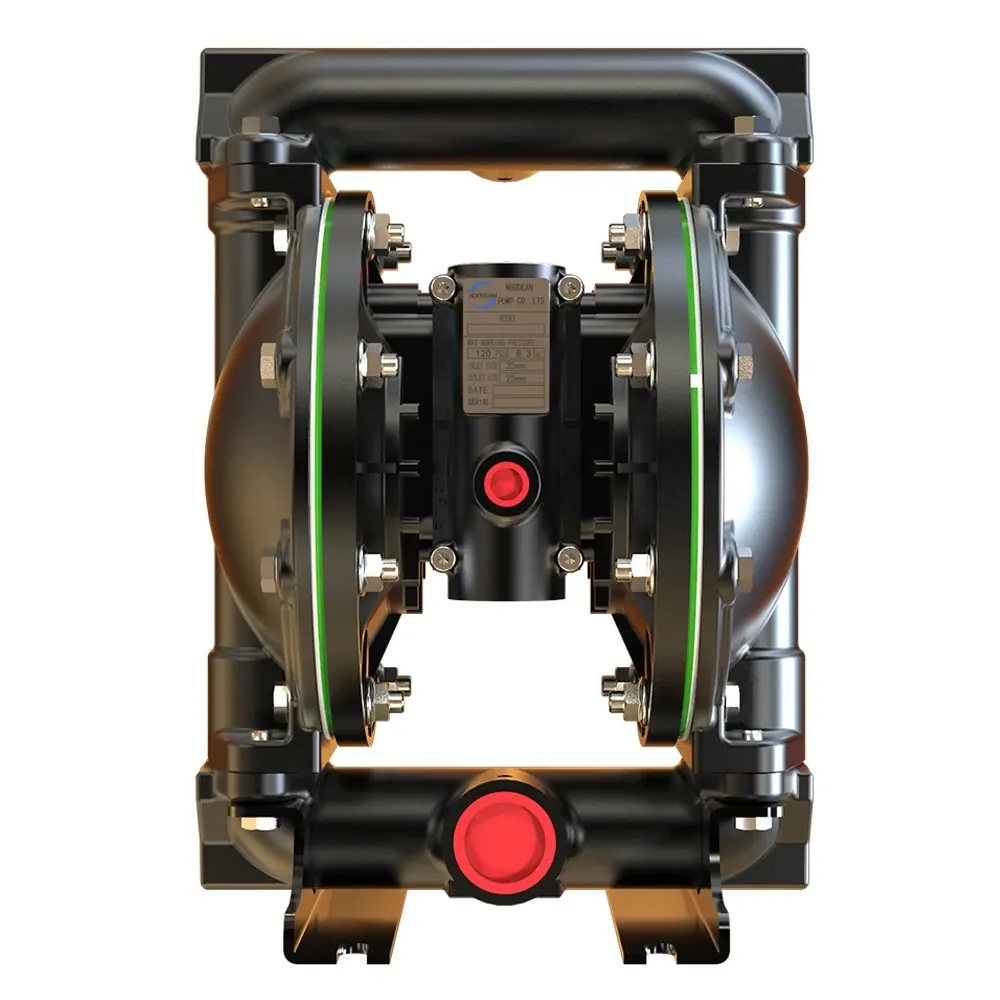
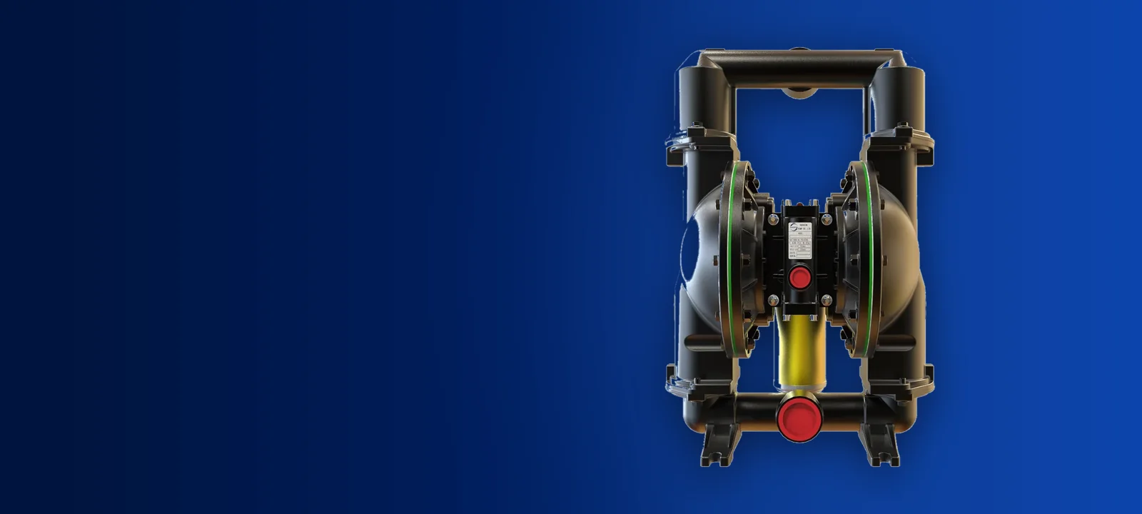
What Stalling Actually Means Inside The Air End
A true stall occurs when the internal air distribution valve stops in a neutral position where neither air chamber receives adequate driving force to complete the stroke. In this state, compressed air may blow straight through the exhaust, or the valve spool sits balanced between opposing pressure ports, leaving the diaphragms motionless.
Maintenance technicians often describe any halted pump as stalled, but mechanical stalling is distinct from hydraulic shutoff. When an operator taps the air valve casing with a rubber mallet and the pump resumes cycling, the issue is almost always a spool that has hung up between shifting ports. Understanding why the valve lost its shifting momentum prevents recurring failures and unnecessary component replacements.
Distinguishing Between A Dead Head And A True Stall
Before disassembling the air mechanism, determine whether the pump has genuinely stalled or if it has simply reached hydraulic balance. An air operated double diaphragm pump will naturally halt whenever fluid discharge pressure equals the incoming air supply pressure. This is normal dead heading rather than a mechanical failure.
To tell the two conditions apart on a running line, isolate the liquid side and inspect the air exhaust port.
- A dead headed pump remains completely silent with zero air blowing from the exhaust muffler because fluid backpressure holds the diaphragm assembly stationary at line equilibrium
- A dead headed pump restarts immediately without intervention as soon as a downstream discharge valve opens or line blockage clears
- A truly stalled pump produces a continuous hiss of blow by air through the muffler while remaining stationary at mid stroke
- A stalled pump fails to restart when discharge lines are depressurised and only cycles if manually jarred or when air supply pressure is surged
The Role Of The Pilot Valve In Preventing Mid Stroke Hangs
Older single valve pump designs rely on main valve spool momentum alone to cross the center transition zone. If air velocity drops or if the diaphragm slows down under high fluid viscosity, the spool often stops dead on center. The DP3X series prevents this condition by dividing the shift into a pilot signal and a power stroke.
In the DP3X air motor, the diaphragm reaches the end of its stroke and mechanically strikes an actuator pin. This pin physically displaces the pilot valve spool. Once moved, supply air rushes behind the pilot spool to secure it in place and immediately directs supply air to the piston face of the major air valve.
Because the shifting force applied to the major air valve spool is pneumatically locked rather than dependent on momentum, the valve shifts over cleanly even when running at very low cycling speeds or throttled air volume. Stalling in this system occurs only when the pilot pin cannot complete its stroke, dynamic seals allow cross leakage, or ice chokes the exhaust flow.
Air Supply Deficiencies That Mimic Mechanical Failure
Many reported air motor stalls are external pneumatic problems rather than internal valve defects. Diaphragm pumps demand instant bursts of air volume at each stroke changeover. A restrictive supply line causes dynamic pressure to collapse at the exact millisecond the major spool attempts to shift.
A static gauge reading at the compressor or filter regulator can be deceptive. A line may register 8.3 bar (120 psi) while the pump sits idle, but drop sharply the moment the valve shifts if the supply pipe, quick disconnect coupling, or regulator orifice is undersized.
To eliminate supply starvation, verify that supply piping matches the air inlet port diameter throughout the run. Avoid coil hoses, restrictive quick couplers, and undersized point of use lubricators or regulators that choke air volume during peak shift demand.
Exhaust Icing And Restriction Problems
Rapid air expansion across the exhaust ports causes a steep drop in temperature. When moisture laden plant air expands, condensed water droplets freeze across the internal muffler pores and exhaust channels. As ice accumulates, backpressure builds inside the air exhaust passage.
When exhaust backpressure matches or nears incoming air pressure, the air chambers cannot vent. Without a pressure differential between opposing diaphragm chambers, the major valve spool cannot complete its stroke and hangs in place. Once the pump sits idle for ten minutes, the ice thaws and the pump runs normally until ice forms again.
The DP3X air motor incorporates a vacuum chamber design that reduces exhaust pressure drop to mitigate ice formation. However, excessive moisture in compressed air lines must still be tackled upstream with coalescing filters and air dryers.
Worn Air Distribution Seals And Pilot Pins
When external air supply and icing have been ruled out, mechanical wear inside the air distribution block is the next checkpoint. Air distribution wear allows cross chamber blow by, robbing the valve of the pressure differential required to drive the spool.
If the dynamic seals on the pilot valve or major spool become worn or scored by pipeline particulate, compressed air leaks across the lands into the exhaust. This cross leakage bypasses the piston face, causing the spool to stall whenever operating against high discharge pressures.
Similarly, if an actuator pin bends or wears short over extended operational cycles, the diaphragm plate cannot displace the pilot spool to its full transition point. The pilot port remains partially blocked, starving the major valve piston of shift pressure.
Step By Step Stall Diagnosis Checklist
Use this sequential checklist to diagnose and rectify stalling on site, working from zero cost external checks down to air motor disassembly.
| Step 1 Check dynamic air pressure | Fit a pressure gauge directly at the pump air inlet. Verify that dynamic pressure during cycling does not fall significantly below operating levels, with 8.3 bar (120 psi) being the maximum catalogue rating. |
|---|---|
| Step 2 Eliminate discharge backpressure | Open discharge valves fully or disconnect the liquid discharge hose into an open vessel to ensure the pump is not simply dead headed against a blocked process line. |
| Step 3 Inspect exhaust muffler for ice and debris | Remove the muffler. If the pump cycles immediately without it, clean or replace the choked muffler element and drain moisture traps upstream. |
| Step 4 Check for continuous exhaust blow by | With air turned on and the pump halted, listen at the exhaust. A continuous air hiss confirms that air is escaping past the major valve spool or through a ruptured diaphragm. |
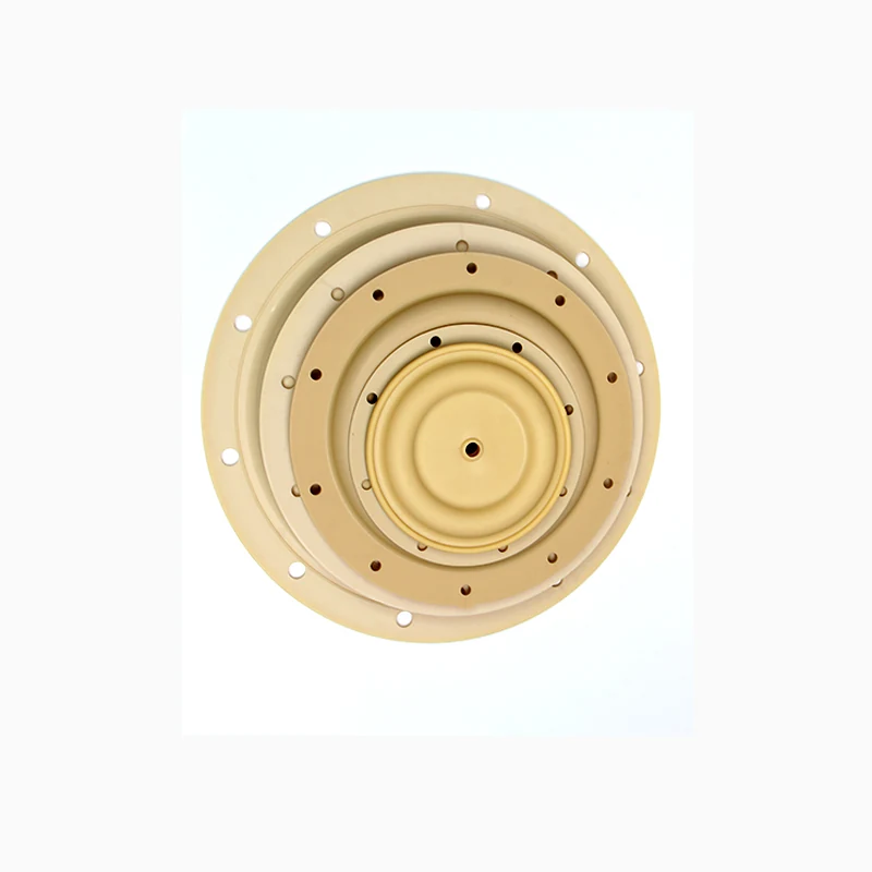
| Step 5 Verify fluid chamber integrity | Check the fluid outlet or exhaust port for liquid contamination. A cracked diaphragm allows fluid into the air distribution section, jamming the spool. |
| Step 6 Inspect pilot actuator pins and valve spool | Isolate air, remove air cap covers, and inspect the actuator pins for straightness and free travel. Clean out particulate and inspect spool seals for scoring or wear. |
Preventing Repeat Stalls In Severe Service
Reliable operation requires clean air and matched piping. For metallic pumps running heavy duty transfer duties, ensuring that air filtration keeps scale and moisture out of the spool carrier prevents almost all mid stroke stoppages.
- Install a dedicated air filter regulator within two meters of the pump air inlet to eliminate dynamic line drop
- Ensure supply hose bore matches or exceeds the pump air inlet connection
- Purge air supply lines before connecting to new installations to blow out pipe scale and welding slag
- Keep air section repair kits on hand to replace worn pilot pins and dynamic seals during scheduled servicing
- On high volume transfer units like the 2 Inch Aluminum Air Operated Double Diaphragm Pump, fit high flow exhaust mufflers to prevent backpressure accumulation