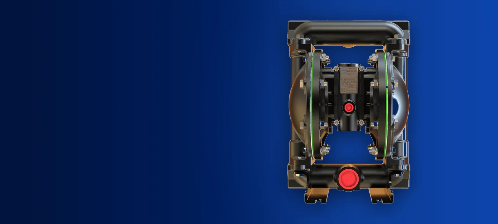
Why Sizing By Pipe Diameter Fails
The most frequent specification error in process plants is matching pump port size directly to existing pipework. A line running 2 inch pipe does not automatically require a 2 inch pump. Piping is frequently oversized to reduce line friction across long distances, or undersized by previous installations with different velocity targets.
Air operated double diaphragm pumps are positive displacement machines. Sizing must be driven by flow rate, total dynamic head, available air volume and fluid characteristics. Forcing a pump selection based solely on manifold flange dimensions leads either to an undersized unit operating at destructive cycle speeds or an oversized unit cycling erratically.
The Reality Behind Maximum Flow Ratings
Every catalogue lists a maximum flow rating for each port size. For example, a 1 inch aluminum pump is rated up to 35 GPM (133 LPM), a 1-1/2 inch aluminum pump reaches 90 GPM (340.7 LPM), a 2 inch aluminum pump reaches 172 GPM (651 LPM), and a 3 inch aluminum pump achieves 237 GPM (897 LPM).
These headline figures represent free discharge conditions where water is pumped at zero discharge head with maximum compressed air input up to 120 psi (8.3 bar). In an actual plant installation with piping runs, elevation change, elbows and process backpressure, the pump will never deliver that catalogued maximum.
Engineers must size for continuous operation at mid curve rather than the extreme boundary. Targeting 40 to 60 percent of maximum rated flow ensures the pump operates with minimal mechanical strain and stable pilot valve shifting.
A Five Step Sizing Procedure
Selecting the correct model requires evaluating process demands in a strict sequence before ordering hardware. Skipping steps usually results in unexpected cavitation, air starvation or premature component failure.
- Determine the required continuous flow rate in liters or gallons per minute
- Calculate the real total head including vertical lift, equipment backpressure and line friction losses
- Verify the site can supply sufficient compressed air volume at operating pressure up to 120 psi (8.3 bar)
- Check required dry suction lift against the model limit, which spans from 17.6 feet (5.4m) to 27.2 feet (8.3m)
- Measure suspended particle dimensions against the ball check clearance of each candidate pump
Running Slower Beats Running Flat Out
Diaphragm life is tied directly to total cycle count. An undersized pump pushed to meet demand must stroke continuously at top speed, accelerating mechanical wear on diaphragms, actuator pins and valve seats. High cycle rates also amplify fluid velocity through the ball check chambers, causing abrasive fluids like slush or cutting fluid to erode the casting.
Selecting a larger pump operating at half speed solves this problem. A 2 inch aluminum pump delivering 90 GPM cycles far slower than a 1-1/2 inch pump delivering that same 90 GPM (340.7 LPM). The larger unit uses less total strokes per batch, runs substantially quieter, and extends mean time between maintenance shutdowns.
Verifying Suction Lift and Suspended Solids
When a pump is installed above the liquid level in waste water treatment or bulk tank transfer, suction lift capability dictates the model choice. A dry suction line requires the diaphragms to evacuate air before drawing fluid into the chambers.
Nuodean aluminum pumps provide specific dry suction lift ratings: the 1 inch pump pulls 20 feet (6.1m), the 1-1/2 inch pulls 19 feet (5.8m), the 2 inch achieves 27.2 feet (8.3m), and the 3 inch pulls 17.6 feet (5.4m). If your vertical lift exceeds these values, the pump will fail to prime without flooded suction.
Solids passage must also be respected to avoid wedging debris beneath the check balls. Standard clearances are 1/8 inch (3.2mm) on 1 inch models, 1/4 inch (6.4mm) on 1-1/2 inch and 2 inch models, and 3/8 inch (9.5mm) on 3 inch models. For heavy slurries containing particles up to 50 mm, a flap valve pump model is required instead of ball checks.
Matching Air Line Supply to Pump Requirements
An air operated pump cannot produce more fluid pressure than the incoming compressed air pressure. At a 1 to 1 ratio, an air supply of 70 psi yields a maximum discharge pressure of 70 psi under stalled conditions. If your process pipe friction and head require 90 psi, the air compressor regulator must supply at least 90 psi directly to the pump inlet.
Restricted air supply lines choke performance. Feeding a 2 inch or 3 inch pump through a narrow 1/4 inch hose causes significant pneumatic pressure drop as soon as the major valve shifts. Always size air drop lines, filters and regulators to match the pump air inlet port so the air chambers fill rapidly on every stroke.
Comparing Four Standard Aluminum Models
The table below outlines baseline performance values across the primary aluminum industrial transfer models for quick reference during preliminary design.
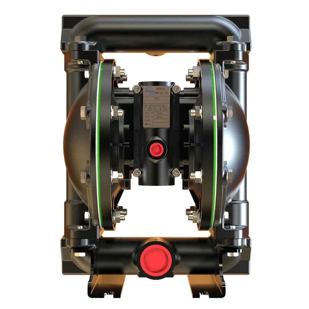
| 1 Inch Aluminum Pump | Delivers up to 35 GPM (133 LPM) and 120 psi (8.3 bar). Handles 1/8 inch (3.2mm) solids with 20 feet (6.1m) dry lift. Weight is 19 lbs (8.6kg) and sound level is 64.5 dB(A) at 70 psi and 60 cycles per minute. |
|---|---|
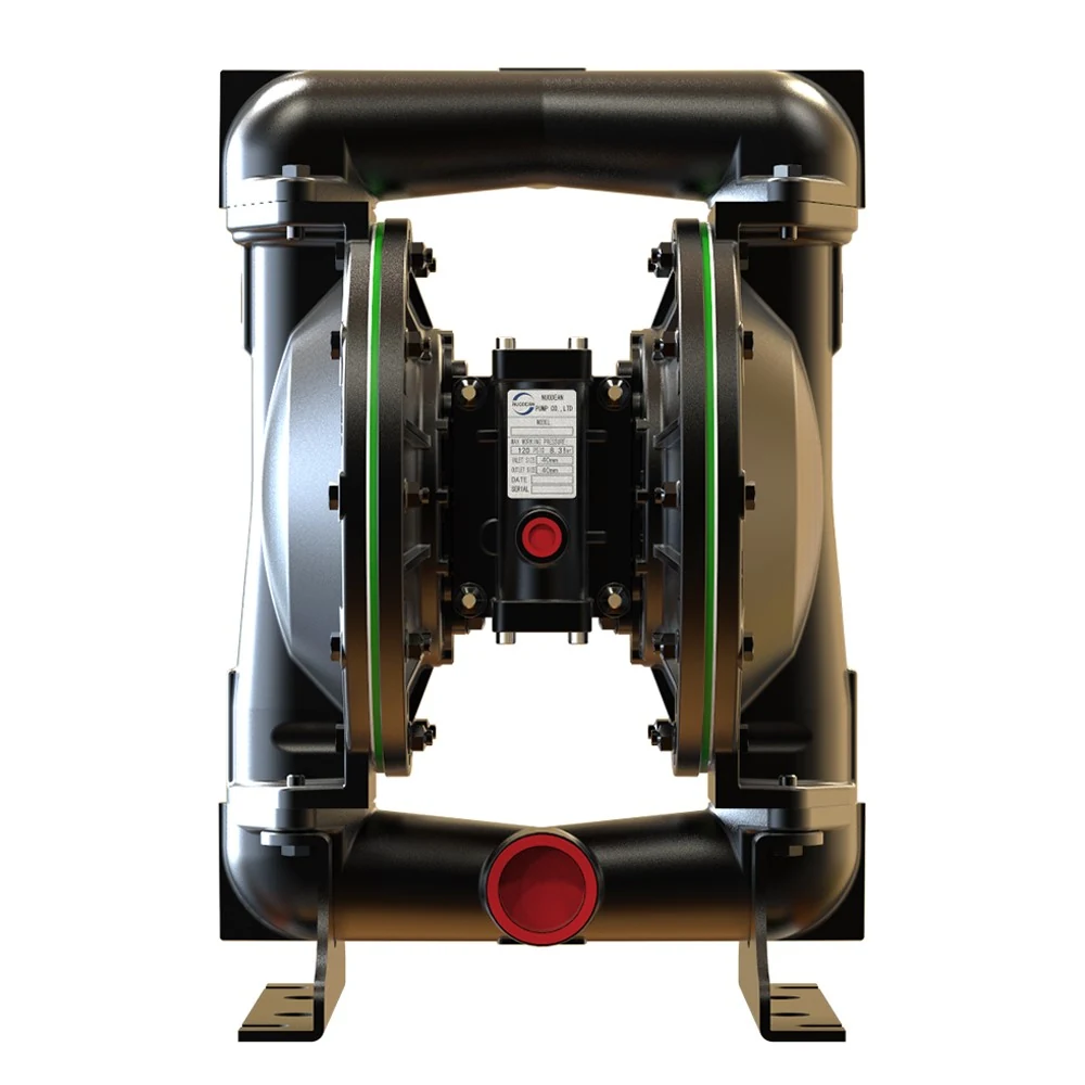
| 1-1/2 Inch Aluminum Pump | Delivers up to 90 GPM (340.7 LPM) and 120 psi (8.3 bar). Handles 1/4 inch (6.4mm) solids with 19 feet (5.8m) dry lift. Weight is 51.5 lbs (23.4kg) and sound level is 80.5 dB(A) at 70 psi and 60 cycles per minute. |
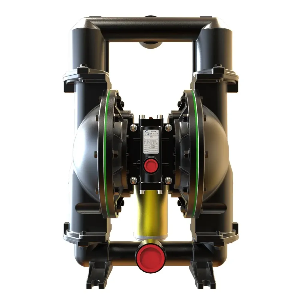
| 2 Inch Aluminum Pump | Delivers up to 172 GPM (651 LPM) and 120 psi (8.3 bar). Handles 1/4 inch (6.4mm) solids with 27.2 feet (8.3m) dry lift. Weight is 65.2 lbs (29.6kg) and sound level is 80.5 dB(A) at 70 psi and 60 cycles per minute. |
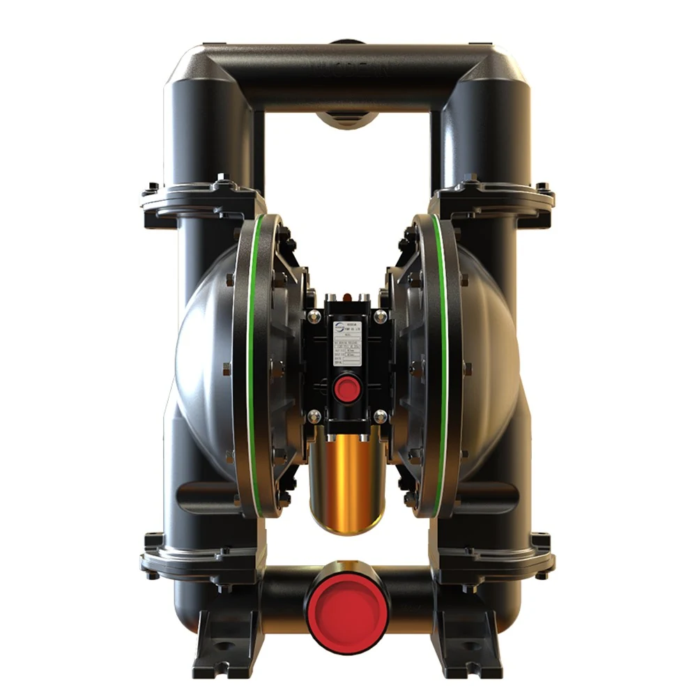
| 3 Inch Aluminum Pump | Delivers up to 237 GPM (897 LPM) and 120 psi (8.3 bar). Handles 3/8 inch (9.5mm) solids with 17.6 feet (5.4m) dry lift. Weight is 109.8 lbs (49.8kg) and sound level is 86.3 dB(A) at 70 psi and 60 cycles per minute. |
Checklist for Sizing Verification
Before signing off on a bill of materials, cross check your system layout against the physical constraints of the air motor and fluid housing.
- Confirm normal operating duty sits inside the middle 50 percent of the flow curve rather than near maximum capacity
- Verify the maximum solid particle in your liquid waste or slurry is smaller than the ball check clearance limit
- Ensure available air supply matches maximum operating pressure up to 120 psi (8.3 bar) without dropping line pressure
- Check chemical compatibility for the fluid chamber casting when pumping solvent, quenching oil, acid or alkali
- Plan pipe support hangers so the manifold castings do not carry the static weight of the connected piping