Daily And Shift Inspection Routine
Most diaphragm pump failures give clear warning signs before fluid escapes into the plant or the air motor halts entirely. A daily walk by inspection takes less than two minutes and catches small leaks before they destroy process hardware.
Begin by inspecting the exhaust port and muffler. The exhaust of an air operated double diaphragm pump should vent clean, cool air. If product is misting or dripping from the exhaust port, a diaphragm has ruptured, allowing pumped fluid to pass into the air chamber and travel through the air valve into the exhaust.
Shut down the air supply immediately when liquid appears at the exhaust. Continuing to run a pump with a breached diaphragm pushes abrasive, corrosive, or viscous process liquid directly into the pilot air valve and major air valve, turning a routine fluid rebuild into a complete air motor overhaul.
Why Air Pressure Must Be Measured At The Pump
One of the most frequent maintenance errors is assuming that compressor receiver pressure matches the air pressure reaching the pump. Long pipe runs, undersized flexible hoses, quick disconnect fittings, and blocked inline filters cause severe pressure drops while the pump is stroking.
Install a pressure gauge right at the pump air inlet, downstream of the local filter regulator. Measure the pressure while the pump is running under full load. A pump rated for a maximum operating pressure of 120 psi (8.3 bar) might show 100 psi on the central compressor, but drop to 45 psi at the inlet during fast cycling because of line restrictions.
Sluggish operation, erratic stroke rates, and nuisance stalling are frequently solved by replacing restrictive supply hoses with adequate line sizes rather than tearing down the air distribution system.
Recognising Check Ball And Valve Seat Degradation
The four check balls and seats govern the suction intake and discharge displacement of the pump. When check valves fail to seal, liquid slips backward across the seat during stroke reversal, causing a sharp drop in flow capacity and suction lift.
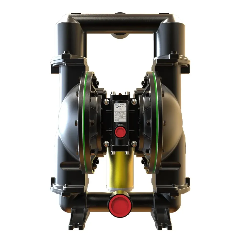
If a pump such as the 2 Inch Aluminum unit suddenly fails to draw fluid from its rated dry suction lift of 8.3 m, inspect the suction check valves first. A pump that cycles rapidly without moving liquid almost always has a stuck, seated, or worn check ball.
- Remove the manifold elbows and inspect the spherical check balls for flat spots, gouges, chemical swelling, or abrasive pitting
- Inspect the check seats for circular groove wear, cracking, or chemical erosion on the sealing contact face
- Examine the check ball guides or cages in the liquid chambers to ensure balls can move freely without sticking at high travel limits
- Replace balls and seats as matched sets, because a new spherical ball will not seal against a grooved or worn seat ring
Step By Step Diaphragm Replacement Protocol
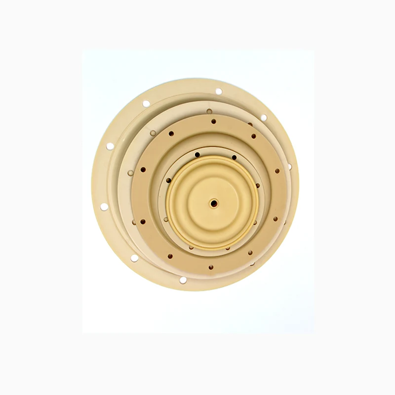
Diaphragms endure millions of flex cycles and represent the primary consumable component in any AODD pump. Replacing them before total rupture avoids fluid contamination of the center section.
Before loosening any fasteners, isolate the compressed air supply and vent all residual pressure from the pump air inlet. Close both the suction and discharge process isolation valves and drain the fluid chambers through the lower manifold drain points or by carefully easing the lower manifold bolts.
Unbolt the outer fluid chambers to expose the diaphragm assemblies. Hold the shaft flat with an open ended wrench or use an internal hex tool on the outer diaphragm plate bolt to loosen the outer plate. Remove the worn diaphragm, inner backup diaphragm if fitted, and inspect the outer piston plates for burrs or corrosion.
When fitting new diaphragms, confirm the flex direction marked on the face. Tighten the diaphragm plates to the central shaft according to manufacturer torque specifications before reattaching the outer fluid chambers.
Fastener Torque Sequence And Bolt Retightening Rules
Pump hardware relaxes under alternating pressure loads, thermal expansion, and mechanical vibration. If fasteners are not maintained, liquid leaks past the outer chamber seals or manifold O-rings, drawing in air during suction strokes and weeping product during discharge strokes.
Always use a calibrated torque wrench and follow a star or crisscross pattern when tightening chamber and manifold bolts. Tightening one side completely before the other pinches the diaphragm perimeter or manifold seal, creating an uneven gap that leaks under pressure.
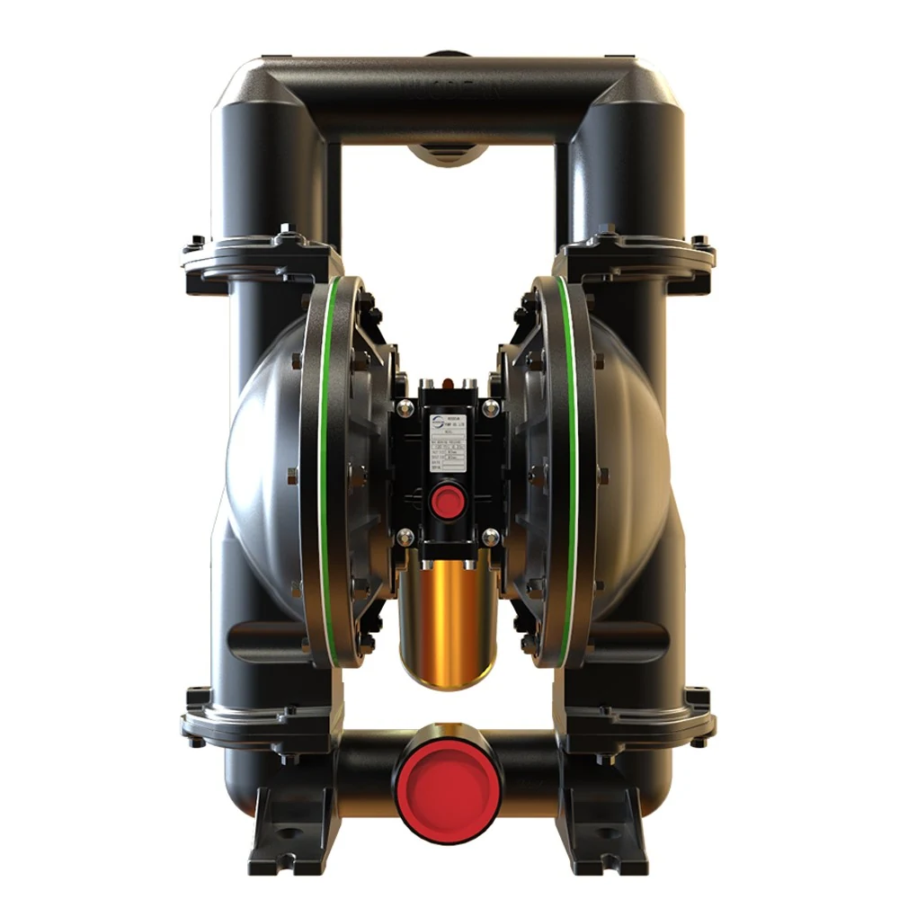
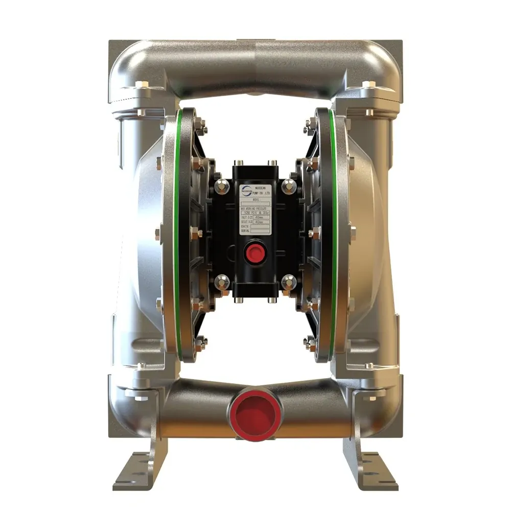
On metallic pumps, such as a 1-1/2 Inch Stainless Steel or 3 Inch Aluminum unit, check fastener torque after the first twenty four hours of operational cycling. Thermal cycling between hot washdown procedures and cold process transfers accelerates joint relaxation, requiring scheduled re-torque checks during monthly preventative maintenance.
Maintaining The Pilot And Major Air Distribution Spools
The DP3X air distribution system relies on a pilot air valve and a major air valve working in sequence. Actuator pins pushed mechanically by the diaphragm end plate shift the pilot valve spool, which then directs air to shift the major valve piston.
Keep air line filters drained of water and clear of scale. Particulate matter entering the air supply scores the valve bores and damages the ceramic dynamic seals. If the pump stalls intermittently, remove the major air valve end caps, clean the spool bore with solvent, inspect the seals for foreign particulate embeds, and verify that the actuator pins slide smoothly in their bushings.
Inspect the exhaust muffler periodically. Particulate debris, compressor oil sludge, or exhaust ice can choke the muffler, building backpressure that prevents the main spool from shifting completely.
Service Schedule And Recommended Actions
Following an organised maintenance schedule avoids unexpected line stops and keeps operating parameters stable across challenging pumping duties.
| Daily Shift Check | Inspect exhaust muffler for liquid discharge, check air inlet pressure gauge under stroking load, and listen for smooth stroke rhythm. |
|---|---|
| Weekly Check | Inspect air line filter bowl for moisture accumulation, clear drain, and verify all external suction and discharge joints are tight. |
| Monthly Inspection | Verify bolt torque on liquid chamber covers and manifold flanges using a crisscross pattern with a calibrated torque wrench. |
| Quarterly Service | Remove exhaust muffler, clean internal baffles from particulate or oil residue, and inspect suction check balls for dimensional trueness. |
| Annual Overhaul | Disassemble fluid chambers, replace diaphragms, check balls, seats, and manifold O-rings using a complete fluid section repair kit. |
Structuring Shelf Spares Between Fluid And Air Kits
Nuodean structures spare parts into two separate packages: fluid section repair kits and air section repair kits. Maintaining this distinction on plant shelves prevents waste and simplifies procurement.
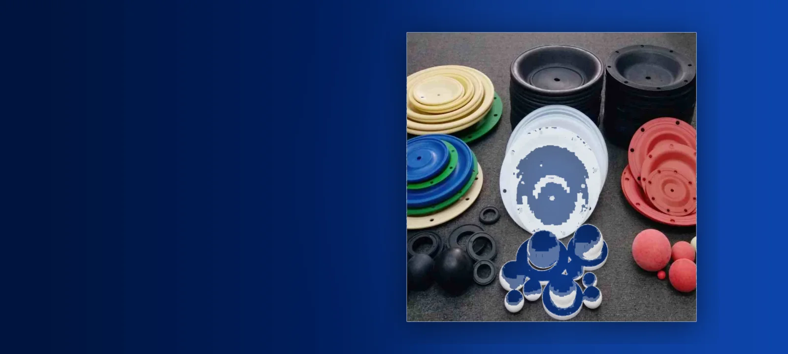
Fluid section repair kits contain diaphragms, check balls, valve seats, and manifold O-rings. Because these components contact the pumped fluid directly, wear rates vary according to abrasion, chemical exposure, and cycle speed. Air section repair kits contain the pilot valve spool assembly, major valve seals, actuator pin O-rings, and air chamber gaskets. Air kits generally last significantly longer if supplied with clean, dry compressed air.
Always consult the pump model code stamped on the serial nameplate when ordering spares. The model code specifies the precise wetted material codes, diaphragm elastomer compound, and valve seat style, ensuring direct compatibility with the installed unit.
- Keep at least one fluid section repair kit on the shelf for every operating pump on critical transfer duties
- Keep one air section repair kit on hand for every three to five pumps operating in the same facility
- Stock spare exhaust mufflers to resolve sudden icing or backpressure restrictions instantly without disassembling the air valve
- Label spare kits with the specific equipment tag number and full Nuodean pump model string