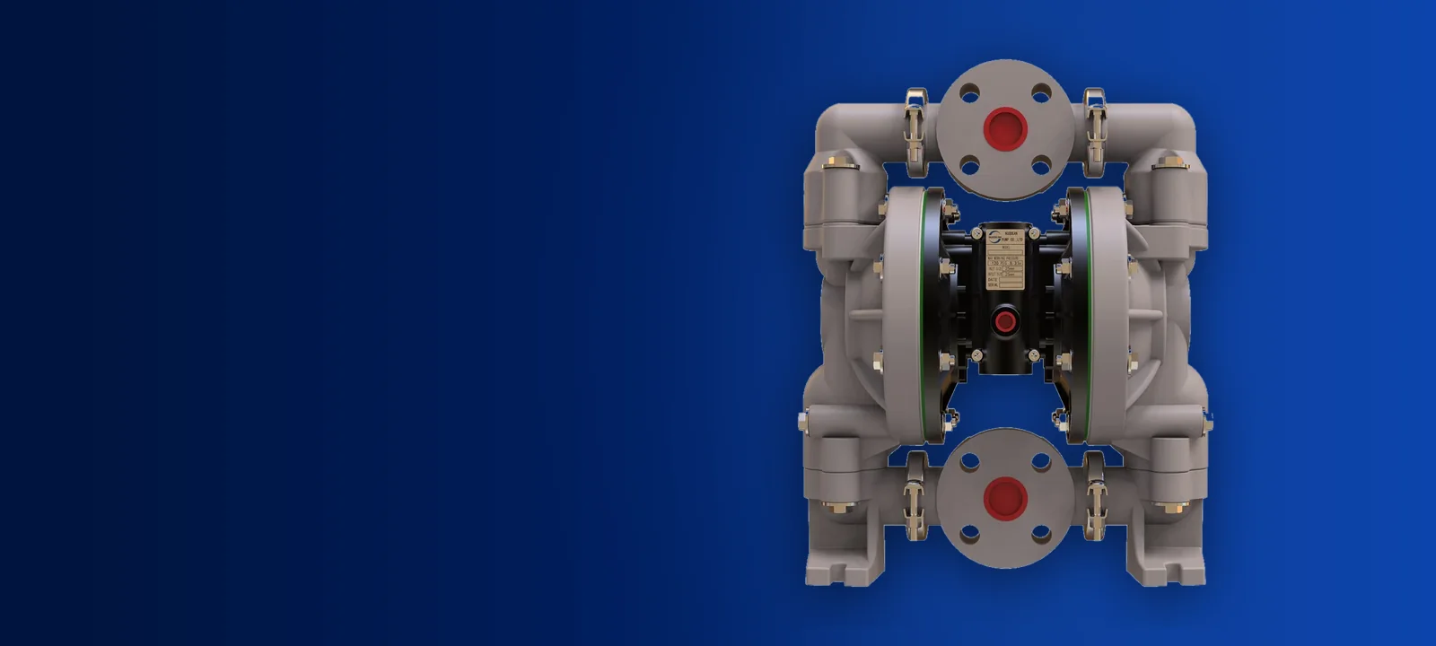
The Physics Behind Exhaust Icing In Diaphragm Pumps
Every air operated double diaphragm pump uses compressed air as its motive power. When air enters the central housing at line pressure, typically between 4 bar and 8.3 bar, it fills one air chamber behind a diaphragm. At the end of the stroke, that volume of pressurised air is vented straight through the exhaust port to the atmosphere.
This rapid expansion causes an immediate temperature drop through adiabatic cooling. As the compressed air drops from supply pressure to atmospheric pressure in milliseconds, the air stream can easily plunge to sub-zero temperatures. If the compressed air line carries ambient moisture, that water vapour condenses and freezes instantly inside the exhaust passages and muffler felt.
The frost restricts exhaust flow. Backpressure builds inside the exhausting air chamber, which fights against the incoming supply air on the opposite side. The pump gradually loses stroke speed, stalls or stops completely. Heating the pump body from the outside does not resolve the root pneumatic problem.
How Anti Icing Valve Chambers Mitigate Freezing
Traditional air valves drop all stored air pressure across a single exhaust orifice. This concentrated expansion produces the sharpest temperature drop directly over the internal valve faces and the exhaust muffler. The DP3X air distribution system counters this mechanism by staging the discharge cycle.
Nuodean incorporates a built-in vacuum chamber within the DP3X air motor assembly. Instead of venting high-pressure air directly into the muffler body, the exhausting air enters an intermediate expansion area that reduces discharge air pressure progressively. Controlling the rate of pressure release spreads the temperature drop across a larger volume, significantly reducing surface frost formation.
Because the pilot air valve and major air valve use ceramic dynamic seals, they do not rely on oil lubrication to slide. Lubricated air sections often suffer from a paste of frozen water and lubricating oil that clogs internal galleries. The lube-free design ensures the internal spools shift freely even when exhaust air temperatures drop near freezing.
- Staged expansion reduces the sharp thermal drop across the exhaust port
- Ceramic dynamic seals eliminate sticky oil and ice emulsions in the valve spool
- Mechanical shift via actuator pins prevents valve hesitation under frost conditions
- Pneumatically assisted spool detention maintains complete strokes during cold runs
What Sound Ratings Mean In Plant Environments
Air motor noise comes from two sources: mechanical valve shifting and the turbulent discharge of compressed air. Nuodean catalogues verify sound levels using a standardized testing baseline of 70 psi supply pressure running at 60 cycles per minute. Sound output varies significantly depending on pump size and housing material.
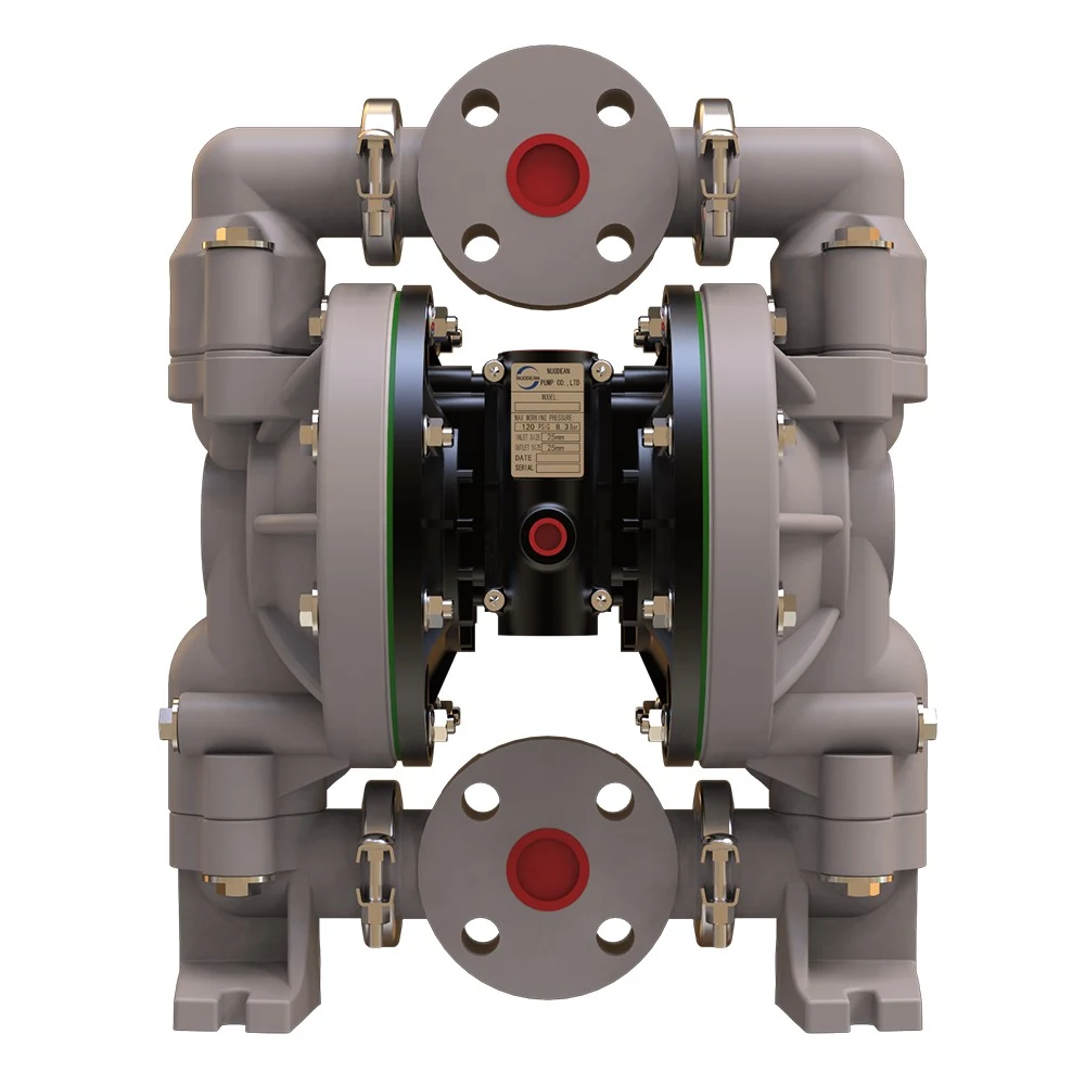
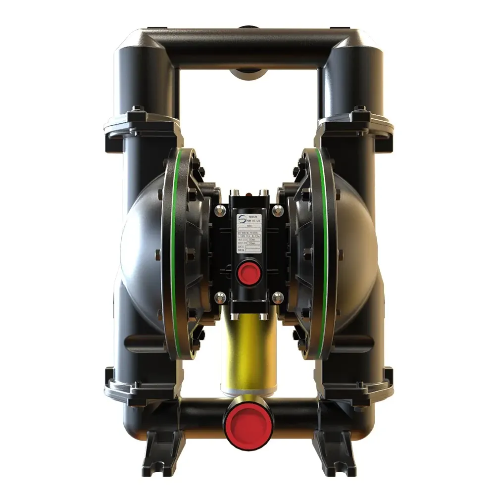
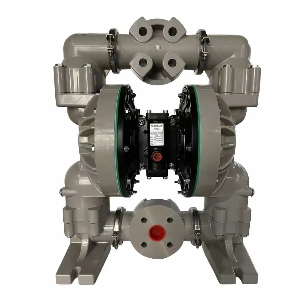
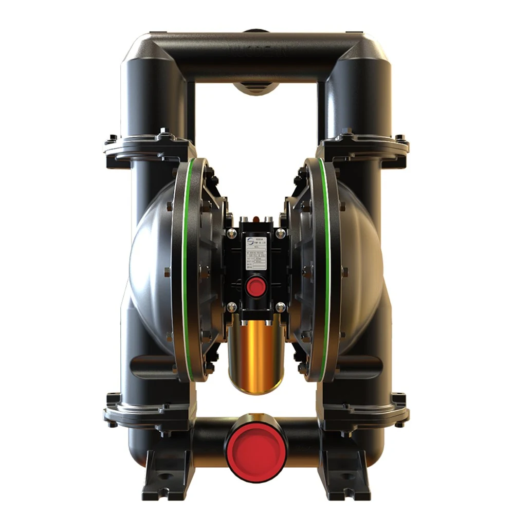
A 1 Inch Non Metallic Air Operated Double Diaphragm Pump emits 64.5 dB(A) under these test conditions, making it suitable for quiet chemical processing rooms. In comparison, the 1-1/2 Inch Non Metallic Air Operated Double Diaphragm Pump operates at 77.7 dB(A). Metallic casings resonate differently: the 2 Inch Aluminum Air Operated Double Diaphragm Pump produces 80.5 dB(A), while the 3 Inch Aluminum Air Operated Double Diaphragm Pump reaches 86.3 dB(A).
Plant engineers must note that noise increases dramatically when a pump runs beyond 60 cycles per minute. Operating an undersized unit at maximum stroke speed creates continuous high-velocity exhaust pulses that exceed 90 dB(A) on factory floors. Sound ratings must always be evaluated alongside actual cycle speed.
How Stroke Frequency And Head Determine Air Consumption
An AODD pump consumes a fixed volume of compressed air for each completed stroke. Each stroke fills one air chamber to the applied line pressure, displacing an equivalent liquid volume before exhausting that air. Consequently, total air consumption is directly proportional to stroke frequency rather than fluid viscosity alone.
Discharge head dictates the minimum air pressure required to keep the pump stroking. If an application requires pumping against 6 bar of fluid discharge head, the air regulator must deliver more than 6 bar to overcome piping resistance and liquid inertia. Feeding 8.3 bar of pressure to run a light transfer duty wastes air, accelerates component wear and deepens exhaust cooling.
Controlling air consumption requires matching the pump displacement to the flow requirement. Running a larger pump at fewer cycles per minute displaces the same liquid flow with lower velocity exhaust pulses. This lowers air demand, reduces continuous noise and prevents the exhaust passage from freezing.
Practical Ways To Reduce Ice And Noise On Duty
Managing pneumatic issues on the factory floor requires addressing supply air quality, exhaust routing and pump sizing. Plant teams can apply four practical engineering controls to keep pumps operating reliably.
- Install refrigerated or desiccant air dryers upstream to remove the atmospheric water that forms ice
- Fit an air filter regulator directly at the pump inlet to feed only the pressure required for the liquid head
- Size the pump up so that stroke speed remains below 60 cycles per minute at the desired liquid flow rate
- Remove the standard muffler and pipe the exhaust air out of the room through smooth rigid tubing
Diagnosing Pneumatic Symptoms On The Factory Floor
When an installation shows signs of sluggish operation or elevated sound, check the pneumatic symptoms before dismantling the fluid manifold.
| Exhaust frost or ice | Moisture in the air line is freezing during expansion. Lower the air pressure, reduce stroke frequency or add upstream air drying. |
|---|---|
| Sudden drop in speed | The exhaust muffler is restricted by ice or solid debris. Inspect the muffler screen and verify air supply dew point. |
| Excessive exhaust noise | The pump is cycling too fast for the application. Throttle the air regulator or step up to a larger pump model. |
| Continuous air blow-by | Air is escaping continuously into the exhaust without pump movement. Inspect the pilot valve spool and major air valve seals for wear. |
| High air consumption | The pump is running against an unthrottled line with excessive pressure. Set the regulator to deliver only the required discharge head. |
Equipment Selection For Balanced Air Demand
Selecting the right pump size determines long-term air efficiency and workplace noise. Pushing a 1 inch non metallic unit to its limit of 177.9 LPM consumes substantial compressed air while cycling near its physical limit, increasing sound well above 64.5 dB(A).
Where higher throughput is required, installing a 2 Inch Aluminum Air Operated Double Diaphragm Pump rated for 651 LPM allows the plant to run the unit at a relaxed 40 to 50 cycles per minute. For heavy bulk transfer duties up to 897 LPM, the 3 Inch Aluminum Air Operated Double Diaphragm Pump delivers massive displacement per cycle, avoiding continuous high-frequency exhaust venting.
Keeping cycle speed moderate protects internal actuator pins, major valve spools and diaphragm plates while eliminating the conditions that cause chronic exhaust freeze.
- 1 inch non metallic units handle light transfer up to 177.9 LPM with low baseline sound
- 1-1/2 inch non metallic units deliver 378.5 LPM for corrosive batching and fluid transfer
- 2 inch aluminum units deliver 651 LPM for general solvent, oil and industrial fluid service
- 3 inch aluminum units deliver 897 LPM for high-volume bulk transfer and tanker unloading