Robot End Of Arm Tooling Holder Selection
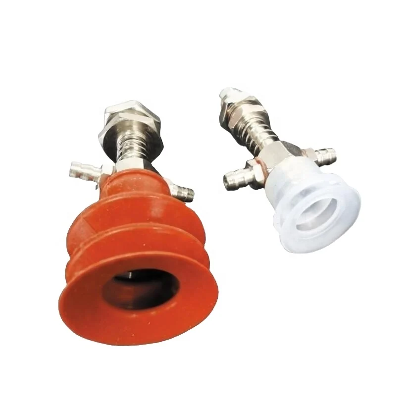
Mrright provides guidance for building the mechanical side of an end-of-arm tooling system. The total weight of the tool and workpiece must remain within the robot's payload limit. Centre of gravity offset is as critical as mass, so balance must be maintained during design. Cross bar diameter should be selected for stiffness over the required reach. Cross clamps are available in matched bore combinations, so bar sizes must be planned together. Spring-loaded cup holders absorb height variation and protect the workpiece on contact; specify stroke and spring rate. Vacuum fittings and hose routing must be planned to avoid interference with robot motion. Tool symmetry reduces twisting moments on the robot arm. Adjustment slots should be included to accommodate part size variations. A quick-change plate is recommended when multiple products use the same robot. A checklist of dimensions is provided before ordering.
Key Design Considerations
Ensure the total tool and workpiece weight stays within the robot's payload capacity. Verify centre of gravity offset against the robot's specifications. Select cross bar diameter based on required reach and stiffness. Match cross clamp bores to the chosen bar sizes. Specify spring-loaded cup holder stroke and spring rate for consistent grip. Route vacuum fittings and hoses to avoid interference with robot movement. Maintain tool symmetry to prevent torque on the robot arm. Include adjustment slots for part size changes. Use a quick-change plate when switching between multiple products on one robot.
Pre Order Checklist
Confirm robot payload capacity and maximum centre of gravity offset. Measure and record cross bar diameter and clamp bore sizes. Define spring-loaded cup holder stroke and spring rate. Plan vacuum fitting locations and hose routing. Verify tool symmetry and balance. Include adjustment slots in the design. Confirm quick-change plate compatibility. Provide all dimensions and mounting details before placing the order.