
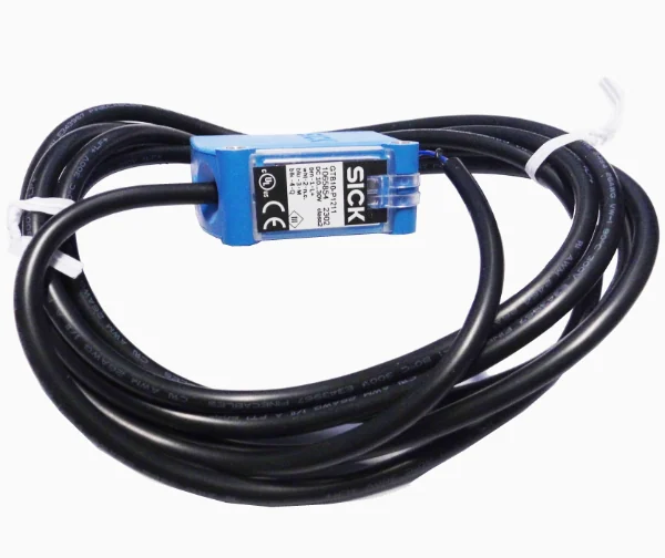
NPN vs PNP Sensor Wiring Explained
This guide addresses the most common wiring error in industrial sensor integration. A PNP sensor switches the positive supply to the input and is standard in Europe. An NPN sensor switches the negative side and is common in Asia. The PLC input card must be wired to match: source inputs for PNP sensors, sink inputs for NPN sensors. A mismatch results in an input that never turns on or one that reads permanently on. This guide covers how to identify the correct sensor type, verify the PLC input configuration, and avoid commissioning delays.
Sensor Type and PLC Input Compatibility
PNP sensors require a source-type input on the PLC. NPN sensors require a sink-type input. Confirm the PLC input type before ordering. Mismatched wiring causes false readings or no response. Use the sensor label to identify the type: PNP typically marked as 'Source' or 'Sourcing', NPN as 'Sink' or 'Sinking'. Check the PLC manual or terminal diagram for the input configuration.
Normally Open vs Normally Closed for Safety
For safety-critical detection, use normally closed (NC) contacts to fail-safe. A break in the circuit triggers an alarm or stop. Normally open (NO) is used for presence detection. Choose based on the machine safety requirement. NC is preferred for emergency stops, door interlocks, and light curtains.
Two-Wire vs Three-Wire Sensors
Two-wire sensors are simpler but require a power supply with a common return. Three-wire sensors have separate power, ground, and signal lines. They are more reliable in noisy environments. Three-wire sensors are standard for PNP and NPN types. Two-wire sensors are used in low-power or space-constrained applications.
Leakage Current and Signal Stability
Leakage current can cause false triggering in low-current circuits. NPN sensors are more prone to this when used with source-type inputs. Use a sensor with low leakage current if the PLC input draws less than 10 mA. Check the sensor datasheet for leakage values. Add a pull-up resistor if needed.
Connector Styles M8 and M12
M8 and M12 connectors are standard for industrial sensors. M8 is used for smaller sensors and lower current. M12 is used for higher power and more robust connections. Check the sensor and PLC connector type before ordering. Ensure the pinout matches the wiring diagram. M12 connectors are often used in harsh environments.
How to Read the Sensor Label
Look for the type: PNP or NPN. Check the output type: source or sink. Note the voltage range and current rating. Identify the connector type: M8 or M12. Confirm the wiring configuration: two-wire or three-wire. Use this information to match the sensor to the PLC input.
Check the PLC Common Terminal Before Ordering
Before placing an order, verify the PLC common terminal type. Is it connected to the positive or negative supply? This determines whether the input is source or sink. Mismatched common terminals cause wiring errors. Confirm the PLC configuration with the manual or terminal diagram.
