
- Home
- Knowledge
- How To Choose Creepage Distance For A Polluted Site
Voltage sets the minimum creepage. The air at the site sets the required one. This guide works through the figures published across our own range to show how the choice is actually made.
Why Voltage Alone Is Not Enough
An insulator rated for the system voltage will hold in clean air. Salt fog, cement dust and industrial fallout deposit a film on the glaze, and once that film is damp the leakage current follows it. The path that was adequate dry is no longer adequate, which is why a line can run for years and then start tripping every wet season after a new plant opens upwind.
Total Creepage And Protected Creepage
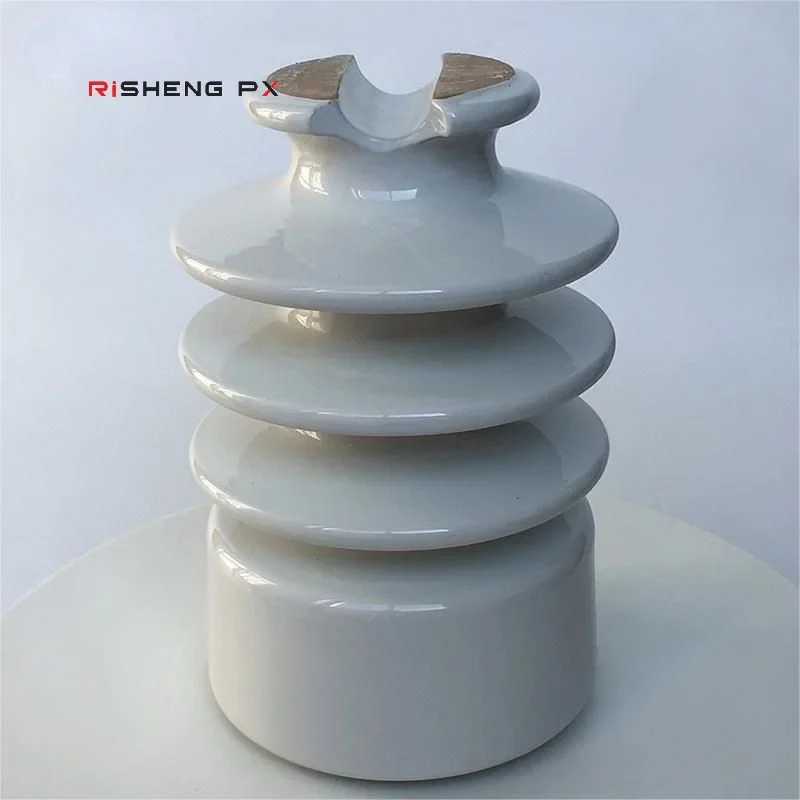
Two insulators with similar total creepage can behave very differently. The QS11404 pin post gives 520mm total with 260mm protected under the sheds. The QS11405 gives 599mm total but only 200mm protected. Where rain washing is unreliable, the protected figure is the better predictor, because it is the part of the path that never gets cleaned by weather.
QS11404 QS11405 IEC Pin Post Insulator 22kV 12.5kN
Getting More Creepage Inside The Same Envelope
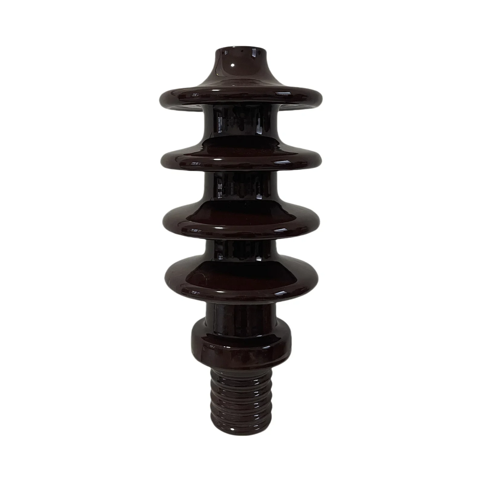
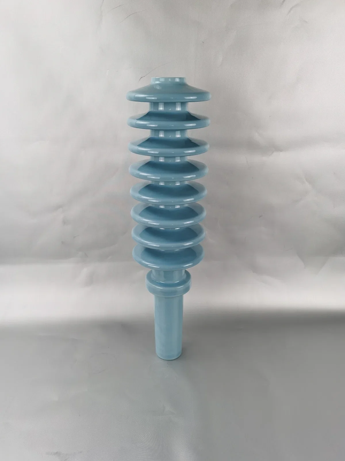
The obvious fix is a larger insulator, and the obvious problem is that it will not fit. Several ranges solve this. The DIN 24kV 630A CD525 bushing carries 525mm of creepage against 440mm on the standard version, on a body 385mm tall and 160mm across that the existing terminal board still accepts.
DIN 24kV 630A Transformer Bushing CD525
Profile As Well As Length
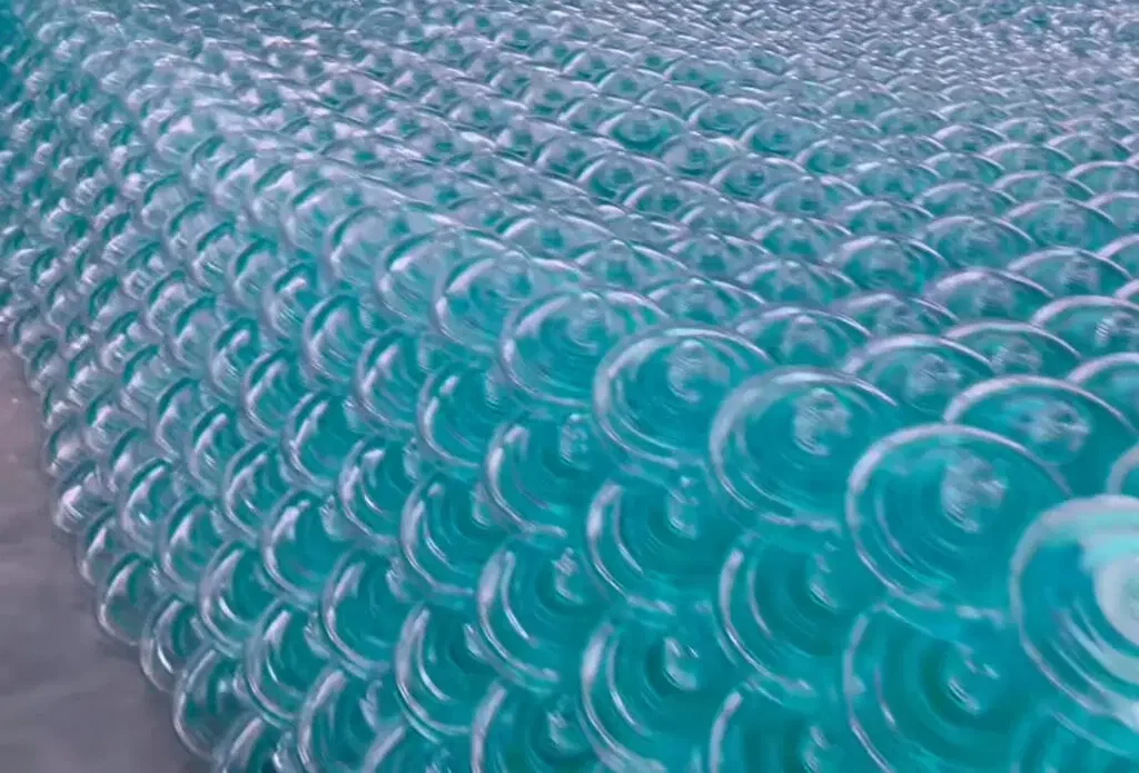
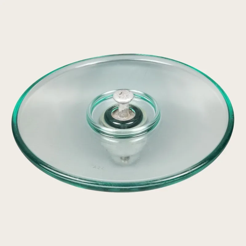
Shape matters as much as length on a dusty site. Aerodynamic profile glass discs are formed so wind carries deposits off the surface instead of letting them settle, which is why that profile is specified in desert and heavily polluted corridors rather than the standard disc.
Aerodynamic Toughened Glass Suspension Insulator XYAY Series
What The Range Actually Offers
Creepage across our production runs from 50mm on a DIN 42530 1kV low voltage bushing, through 180mm on the AS SLP11180 pin insulator, 305mm on ANSI 55-5, 450mm on the ALP22-450, 600mm and 770mm on the ZS pin posts, 900mm on the P-33-Y, 935mm on the EN 36/250/P3 bushing and 1015mm on the ANSI 57-14 line post. The right figure is somewhere in that span, and it comes from the site.
ZS-770 Pin Post Porcelain Insulator 770mm Creepage
Verifying What You Received
A creepage specification you cannot check on delivery is not a specification. Creepage is verified against the drawing figure on routine inspection here, and where a tolerance band applies it is published, such as 400mm plus or minus 10mm on the ShF-20G1 pin insulator.
ShF-20G1 Ceramic Pin Insulator 400mm Creepage
Products Referenced In This Guide
High Voltage Transformer Bushings
DIN 24kV 630A Transformer Bushing CD525
Pin Type Insulators
- Creepage Distance 525 mm
- Net Weight 6.8 kg
- Height 385 mm
ZS-770 Pin Post Porcelain Insulator 770mm Creepage
Glass Suspension Insulators
- Creepage Distance 770 mm
- Rated Electromechanical Failing Load 16 kN
- Lightning Impulse Withstand Voltage 190 kV
Aerodynamic Toughened Glass Suspension Insulator XYAY Series
High Voltage Transformer Bushings
- Rated Mechanical Failing Load 120 kN
- Nominal Creepage Distance 365 mm
- Power Frequency Puncture Voltage 130 kV
EN 36/250/P3 Transformer Bushing Insulator 36kV
- Voltage 36 kV
- Height 600 mm
- Diameter 155 mm
Related Ranges And Applications
Pin Type Insulators
Transformer Bushing Insulators
Power Utilities And Substations
Overhead Line Contractors
Selecting Creepage For The Pollution At Your Site
Questions About This Topic
Apply This To Your Own Project
Send the drawing or describe the site and we will recommend a pattern and a creepage class.
Product Photographs
Request a Quote
We reply to every enquiry within one business day. Write to us directly by email or WhatsApp — both reach our sales desk immediately.